4/8 tone CTCSS encoder

Last updated: August 31, 2012

CTCSS encoder

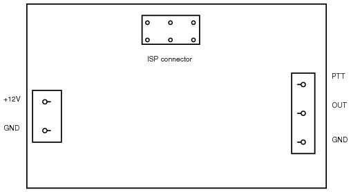
Connections


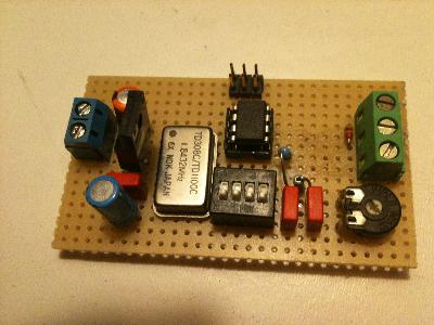
The encoder is based on a 32 bit DDS generator. The output is a PWM signal. After the low-pas filter this becomes a reasonably clean sine.

[ctcss.png]

Specifications

Switches

Pin 1 RST:
Pin 1 I/O (not tested)

Results


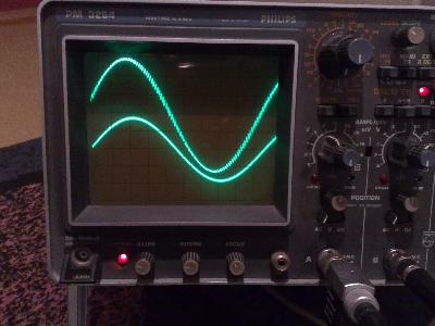
Upper trace: signal after 1st RC section
Lower trace: signal after 2nd RC section
Photo: PE1GGX

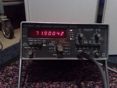
Specification: 71.9 Hz +/- 0.4% ;-)
Photo: PE1GGX

Implementation notes

The ATtiny13 8 bit timer is driven by the system clock of 1.8432 MHz. Every 256 clock ticks a Timer Overflow interrupts is generated and the Output Compare Register is updated. This give a 'DDS frequency' of 7200 Hz. This is more than sufficient to generate sines in the 70 - 80 Hz range.

The code contains a table with 8 DDS phase increments (ctcss_inc). PB5, PB4 and PB2 are used as an index in this table. If Pin 1 of the ATtiny13 is used as RST only the first 4 entries are used. PB5 is read as '0'. If Pin 1 is used for I/O all 8 entries are used.

When PTT is high the microcontroller goes into a power-save mode. This is rather useless, because the TCXO draws more than 40 mA. The power save mode saves 0.1 mA (measured). If power usage is an issue, another type of microcontroller that supports an external Xtal and power-save modes (ATtiny25, ATtiny45) should be used.

The Archive contains a program to calculate phase increments (calc_inc.c) and a program to calculate a sine table (sin_table.c)

Programming

The improved STK200 programmer (local copy), connected to a FreeBSD 8 system with avrdude, has been used for this project. This programmer does not support Atmels HVSP prorgramming mode.
The low fuse byte must be set to 0x7A (external CLK input), the high fuse byte remains 0xFF.

Downloads

Archive containing the Xcircuit files (encapsulated postscript) and the software.