CC1000
A Low Power Embedded Linux system
Manual v 0.3
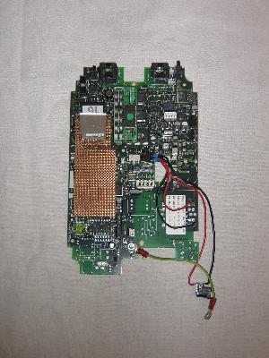 |
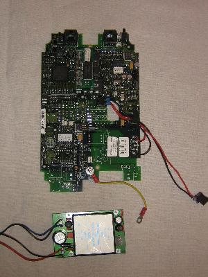 |
4MB CC1000
with MMC/SDcard piggyback
|
8MB CC1000
with DC-DC converter
|
This manual is a subset of the CC1000
project information on PA3HDF's website. Updated and/or more
information might be available.
Content:
Getting started
To get started connect a power supply, connect the console port of
the CC1000 to a terminal or a PC with a terminal emulator with the
speed set to 9600 bps and connect the Ethernet port to your
hub.
If you choose to use the DC-DC converter the power supply should
deliver something between 35V and 75V. If you do not use the DC-DC
converter connect a 15V @ 0.5A supply. In both cases mind the
polarity, a protection diode does not hurt.
After applying power abort the boot sequence by hitting a key. Now
have a look at the preconfigured environment settings with the
'printenv' command. The default IP address of the CC1000 is
192.168.0.100. You can change is to e.g. 10.0.0.100 with the
'setenv' command:
=> setenv ipaddr 10.0.0.100
Use 'setenv' to change other settings if needed. Save the new
settings to flash with:
=> saveenv
Now restart with 'boot' or simply push the reset button next to the
console connector.
After a while you will have a running Linux system with a shell
attached to the console port.
Modifying startup
At startup the CC1000 executes /etc/rc.sysinit. If you do not have
a configured data partion the CC1000 does some basic
initialisations and after that starts an HTTP server.
Both the 4MB and 8MB flash versions of the CC1000 have the
possibility to add a SDcard. The 8MB version also has a 4MB JFFS2
partion which is used for a data partition. The data partition is
mounted on /u02 (old versions may use /data instead).
/etc/rc.sysinit tries to mount /u02 and if it
finds a second startup script, /u02/etc/rc.sysinit, this script is
executed.
Mounting the data partition is configurable with the U-Boot environment
variable 'mountcmd'. The 4MB CC1000 has a dummy mountcmd, the default for
a 8MB CC1000 is
setenv mountcmd mount -t jffs2 /dev/mtdblock0 /u02
For a SDcard you might want to use something like
setenv mountcmd mount -t ext2 /dev/mmca1 /u02
Do not forget to update the environmnet with 'saveenv'.
Example /u02/etc/rc.sysinit:
        #!/bin/sh

        # Services
        /usr/sbin/httpd -h /u02/www
        /usr/sbin/bftpd -d -c /u02/etc/bftpd.conf
        /usr/bin/rsync --daemon --config=/u02/etc/rsyncd.conf --address=192.168.0.100
        /usr/sbin/dropbear -d /u02/etc/dropbear_dss_host_key -r /u02/etc/dropbear_rsa_host_key
Do not forget the 'chmod +x /u02/etc/rc.sysinit'.
The HTTP server is started with another DocumentRoot.
Starting a FTP server is not really needed, because dropbear also
supports scp.
If you choose to update your data, e.g. your website, with RSYNC
and you have to use the RSYNC protocol, RSYNC should be
started.
Dropbear is a sshd server with a low memory profile. If you use it
in combination with RSYNC, the standard RSYNC configuration, there
is no need to start RSYNC.
Dropbear expects host keys. Generate these with:
        cd /u02/etc
        dropbearkey -t rsa -f dropbear_rsa_host_key
        dropbearkey -t dss -f dropbear_dss_host_key
The CC1000 comes with a passwd file. The 'root' and 'user' accounts
have password 'cc1000'. To change this a new passwd file should be
written to /ramdisk/etc/passwd during startup.
Hardware
The CC1000 consists of a main PCB, a frontpanel PCB and a DC-DC
converter. The main PCB has:
- A MPC823 PowerPC running at 64MHz
- 4 or 8MB flash memory
- 8MB dynamic RAM
- A 10Mbps Ethernet port
- A RS232 serial console port
- Miscellaneous components, e.g. a Toshiba Neuron chip
The frontpanel PCB contains several connectors, of which only the
Ethernet (RJ45) and serial port connector (DB-9) are usefull.
The DC-DC converter delivers 15V at 1.3 Amps from an input voltage
of 36 - 75V.
Main PCB
![[cc1000_pcb.png]](cc1000_pcb.png)
Connector J802
| Pin 1 |
+5V |
Pin 26 |
? |
| Pin 2 |
? |
Pin 25 |
? |
| Pin 3 |
PortD_14 / MMC_DI |
Pin 24 |
SMCRX2 |
| Pin 4 |
+3.3V |
Pin 23 |
? |
| Pin 5 |
GND |
Pin 22 |
? |
| Pin 6 |
Vin LM2940 |
Pin 21 |
? |
| Pin 7 |
GND |
Pin 20 |
PortC_6 |
| Pin 8 |
PortD_15 / MMC_DO |
Pin 19 |
PortD_6 / MMC_CLK |
| Pin 9 |
? |
Pin 18 |
PortC_5 |
| Pin 10 |
? |
Pin 17 |
SMCTX2, Remark 1 |
| Pin 11 |
? |
Pin 16 |
? |
| Pin 12 |
? |
Pin 15 |
? |
| Pin 13 |
PortD_10 / MMC_CS |
Pin 14 |
? |
Remarks:
1) Remove U801 and connect pads U805-5 and U801-8 to get SMCTX2 on
pin 17.
Switch S900
S900 is connected to PortC_7.
Memory layout
| Address range |
Usage |
| 0x00000000-0x0003ffff |
Base RAM |
| 0x00400000-0x007fffff |
Piggyback RAM |
| 0xff800000-0xffbfffff |
Flash, data partition (8MB version only) |
| 0xffc00000-0xffefffff |
Flash, root filesystem |
| 0xfff00000-0xfff1ffff |
U-Boot |
| 0xfff20000-0xfff3ffff |
U-Boot Environment (4KB used) |
| 0xfff40000-0xffffffff |
Kernel |
Software
The CC1000 uses U-Boot and a Linux 2.4 kernel from the The DENX
U-Boot and Linux Guide (DULG).
The U-Boot manual is here.
The main user level software is Busybox version 1.8.1 with almost all
modules enabled. Besides Busybox the root filesystem (3MB flash)
contains:
- The BFTPD version
2.1 FTP server.
- RSYNC version
2.6.9
- The DROPBEAR
version 0.50 SSH client and server.
- SPORTD a small serial port daemon.
- This manual
Development environment
The environment to develop the CC1000 software is the Embedded Linux Development Kit
version 4.1 from Denx Gmbh. See the Denx website for full
information of the ELDK.
The ELDK gives you a full development environmnet except a debugger
(GDB). The main website contains information on how to build a
debugger youtselves.
Hardware modifications
Console cable
A RS232 adapter cable needs less space then the front panel
PCB.
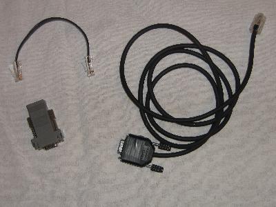 |
2 adapter cables.
A RJ45 <> DB9 adapter with a straight cable (left)
A RJ45 cable soldered directly to a DB9 connector (right) |
The RJ45 console connector of the CC1000 is compatible with the
Yost
serial device wiring
Yost DB9 to RJ45 serial DTE adapter wiring
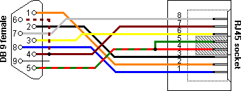
| RJ45 |
Function |
Color |
DB9 |
Remark |
| 1 |
CTS |
Blue |
8 |
Connected, not used |
| 2 |
CD |
Orange |
1 |
Connected, not used |
| 3 |
Rx |
Black |
2 |
Connected, used |
| 4 |
SG |
Red |
5 |
Connected, used |
| 5 |
SG |
Green |
5 |
Not connected |
| 6 |
Tx |
Yellow |
3 |
Connected, used |
| 7 |
DTR |
Brown |
4 |
Connected, not used |
| 8 |
RTS |
White |
7 |
Connected, not used |
A DB-9 <> RJ45 cable connections:
| DB-9 |
RJ45 |
MAX3232 |
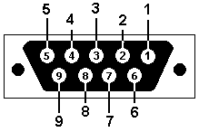
Front view |
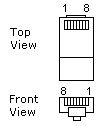 |
 |
| 2 |
3 |
3 |
| 3 |
6 |
4 |
| 5 |
4 |
2 |
Check your cable with an ohm-meter between the MAX3232 and DB9
connector.
MMC/SDcard interface
4 signals of IO Port D of the MPC823 are available on the J802
connector. These signals are used for a MMC/SD interface.
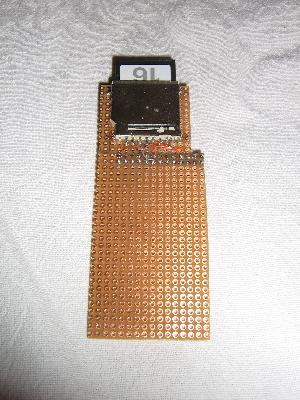 |
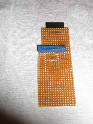 |
| Piggyback front view |
Piggyback back view |
The 4MB version of the CC1000 has a pin header on connector J802.
This header is a suitable mounting point for a piggyback with a
MMC/SDcard connector and the second serial port. The 8MB CC1000
does not have this pin header. Use wires to connect the MMC/SDcard
connector.
![[cc1000_mmc_sd.png]](cc1000_mmc_sd.png)
![[mmc_sd_contacts.jpg]](mmc_sd_contacts.jpg)
| MMC/SD signal |
MMC/SD connector |
Port D signal |
Port D mask |
J802 connector |
| CS |
1 |
PD10 |
0x0020 |
13 |
| DI |
2 |
PD14 |
0x0002 |
3 |
| GND |
3 |
- |
- |
5 |
| Vcc (3.3V) |
4 |
- |
- |
4 |
| CLK |
5 |
PD06 |
0x0200 |
19 |
| GND |
6 |
- |
- |
5 |
| DO |
7 |
PD15 |
0x0001 |
8 |
The installed kernel has a MMC/SD device driver that uses the SPI
mode.
Transfer speed reading: approx. 275 KB/sec.
Transfer speed writing: approx. 133 KB/sec.
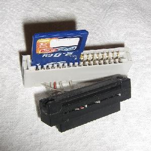 |
Alternative connectors are an old floppy disk connector or an
ISA bus connector (use the small one). Do not insert the card too
far into a floppy or ISA connector, the card won't make
contact. |
Second serial port
The TxD and RxD lines of SMC2 are on J802. Connecting a RS232 level
convertor (MAX232, MAX202 etc.) gives the CC1000 a second serial
port.
![[cc1000_serial2.png]](cc1000_serial2.png)
The piggyback has enough room for this. If you do not use a
piggyback board, use wires to connect the port to J802.
Remarks:
- To get +/- 10V signals from the RS232 level convertor, the
convertor must be powered with 5V. The MPC823 ports cannot handle
5V signals, so the Tx signal from the convertor is divided down to
approx. 3V with resistors. The Rx input works fine with a 3V
signal.
- SMCTX2 is connected to U801-8, U801-5 is connected to J802-17.
If you want to use J802 for all connections U801-5 must be
connected to U801-8. Remove U801 if it is mounted.
- +5V and GND are on J802-1 and J802-5.
- Check the datasheet of the convertor for capacitor values.


![[cc1000_pcb.png]](cc1000_pcb.png)


![[cc1000_mmc_sd.png]](cc1000_mmc_sd.png)
![[mmc_sd_contacts.jpg]](mmc_sd_contacts.jpg)

![[cc1000_serial2.png]](cc1000_serial2.png)