CC1000 hardware
Last updated: februari 8, 2008
Under construction
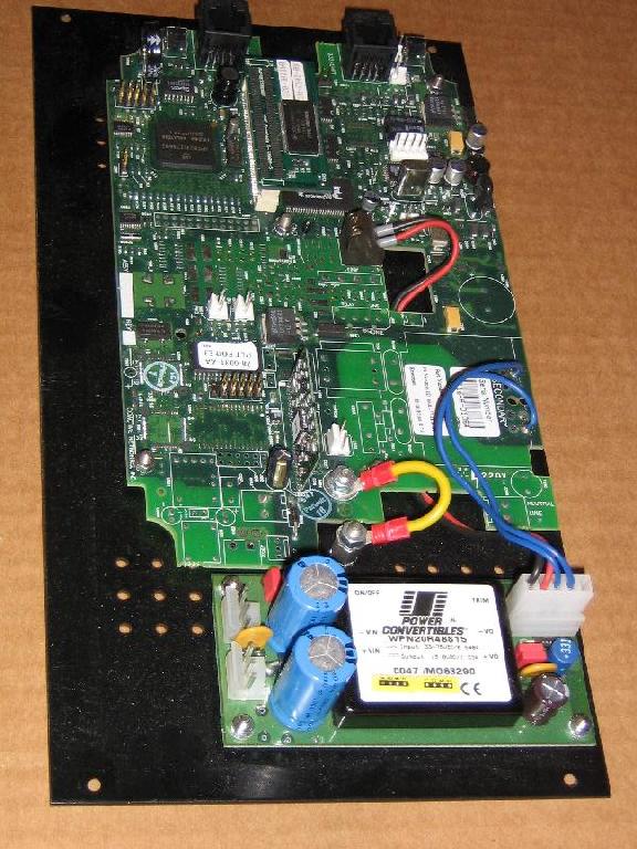
The CC1000 board contains:
- A MPC823 PowerPC CPU running at 64MHz
- 2Mx16 SDRAM
- 2Mx16 SDRAM on a separate board
- 2Mx16 or 4Mx16 Flash ROM
- A 10 Mbps Ethernet interface
- A SP3232 RS232 level translator
- A LONtalk chip
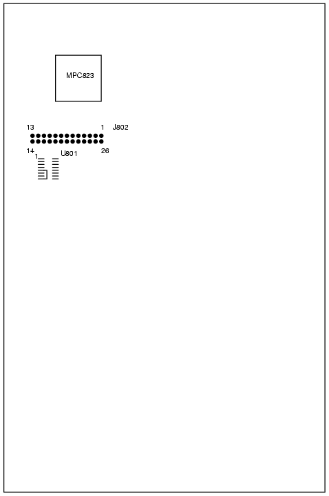
Connector J802
(all connections should be checked before use):
| Pin 1 | +5V |
Pin 26 | ? |
| Pin 2 | ? |
Pin 25 | ? |
| Pin 3 | PD14 / MMC_DI |
Pin 24 | SMCRX2 |
| Pin 4 | +3.3V |
Pin 23 | U801-5 |
| Pin 5 | GND |
Pin 22 | U801-10, U801-12 |
| Pin 6 | Vin LM2940 |
Pin 21 | ? |
| Pin 7 | GND |
Pin 20 | PC06 |
| Pin 8 | PD15 / MMC-DO |
Pin 19 | PD06 / MMC_CLK |
| Pin 9 | U600-19 |
Pin 18 | PC05 |
| Pin 10 | ? |
Pin 17 | SMCTX2 (Connect U801-5 and U801-8) |
| Pin 11 | U600-13 |
Pin 16 | U600-17 |
| Pin 12 | U600-14 |
Pin 15 | U600-16 |
| Pin 13 | PD10 / MMC_CS |
Pin 14 | U600-18 |
Memory initialisation is done in the U-BOOT code:
	0x00000000 - 0x003fffff :	RAM (BR1)
	0x00400000 - 0x007fffff :	RAM (BR4)
	0xff800000 - 0xffffffff :	ROM (BR0)
Ports
Port A
(all connections should be checked before use):
| Signal | Function | Connected to |
| PA04 | CLK4 | Ethernet RCLK input from LXT905 |
| PA05 | - | - |
| PA06 | CLK2 | Ethernet TCLK input from LXT905 |
| PA07 | - | U801-3 |
| PA08 | SMTXD2 | U801-5 |
| PA09 | SMRXD2 | U801-6 |
| PA10 | - | - |
| PA11 | - | - |
| PA12 | TXD2 | TX output to LXT905 |
| PA13 | RXD2 | RX input from LXT905 |
| PA14 | - | - |
| PA15 | - | - |
Port B
(all connections should be checked before use):
| Signal | Function | Connected to |
| PB16 | - | - |
| PB17 | PB17 | LBK of LXT905 |
| PB18 | - | U600-14 |
| PB19 | - | - |
| PB20 | - | - |
| PB21 | - | - |
| PB22 | - | - |
| PB23 | - | - |
| PB24 | SMRDX1 | RS232 converter |
| PB25 | SMTDX1 | RS232 converter |
| PB26 | - | - |
| PB27 | - | - |
| PB28 | - | - |
| PB29 | - | - |
| PB30 | - | - |
| PB31 | - | - |
Port C
(all connections should be checked before use):
| Signal | Function | Connected to |
| PC04 | - | U801-2 |
| PC05 | - | - |
| PC06 | - | - |
| PC07 | - | S900 |
| PC08 | PC08 | Ethernet Receive Enable ? |
| PC09 | PC09 | COL signal from LXT905 |
| PC10 | - | - |
| PC11 | - | - |
| PC12 | - | - |
| PC13 | - | - |
| PC14 | PC14 | TEN signal to LXT905 |
| PC15 | - | - |
Port D
(all connections should be checked before use):
| Signal | Function | Connected to |
| PD03 | - | - |
| PD04 | - | U801-8 |
| PD05 | - | U801-7 |
| PD06 | - | J802-19, MMC_CLK |
| PD07 | - | - |
| PD08 | - | - |
| PD09 | - | - |
| PD10 | - | J802-13, U600-12, MMC_CS |
| PD11 | - | - |
| PD12 | - | U600-18 |
| PD13 | - | - |
| PD14 | - | J802-3, MMC_DI |
| PD15 | - | J802-8, MMC_DO |
Power consumption:
| 12V | 253mA |
| 13V | 234mA |
| 14V | 218mA |
| 15V | 205mA |
| 16V | 194mA |
| 17V | 185mA |
| 18V | 178mA |
| 19V | 172mA |
| 20V | 168mA |
The LM3940-3.3 gets slightly warm at 20V.
If the on-board LM2940 regulator is used the power supply should be at least
12.5V according to the National Semiconductor datasheet.